Easy-tune vertical dipole
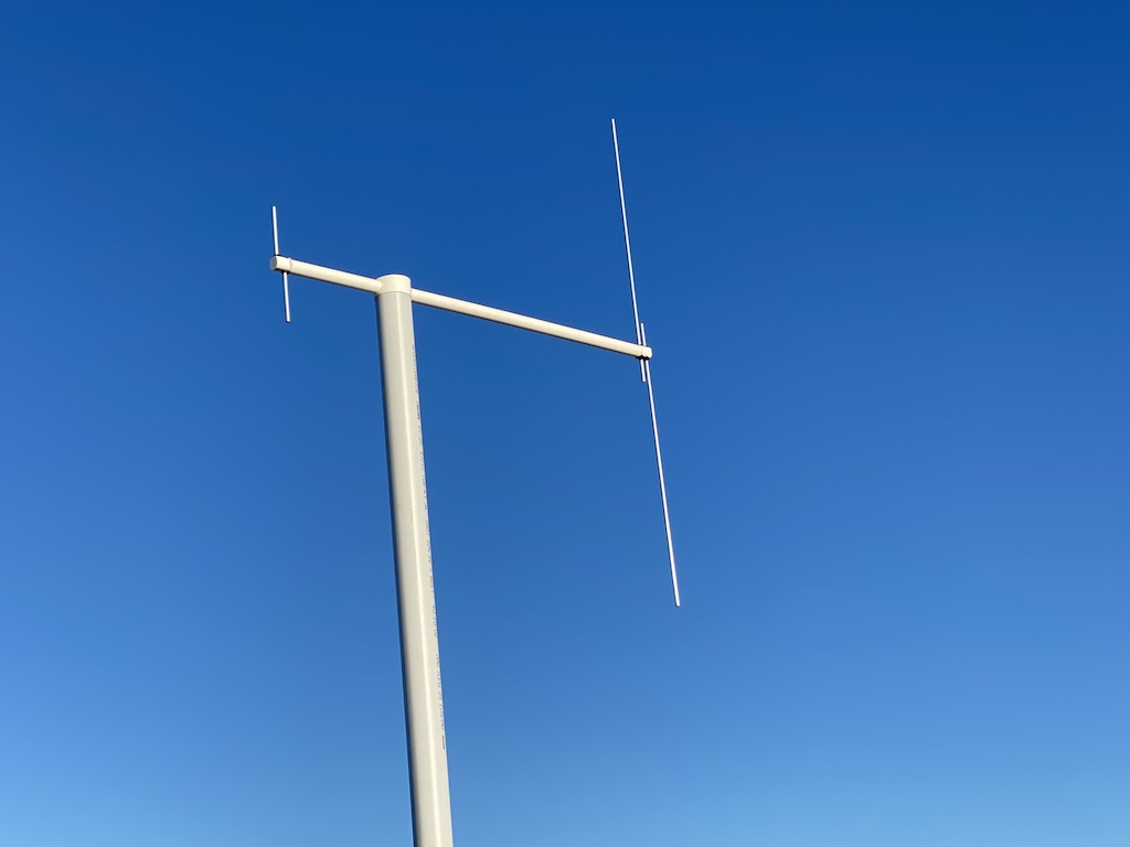 Two of my vertical dipole antenna against the sky. One for 2m and the other for 70cm.
This is a take on the humble vertical dipole antenna for 2m, and it can be made for other bands. This antenna features a 3D printed bracket that allows it to be tuned by making small changes to the electrical length of two aluminium rods held in place with small screws.
What you need
| Item | Description | Link |
|---|---|---|
| 1x 3D printed bracket | You need one per antenna | Download |
| 1x T50-17 toroid | Used to make a balun | Minikits |
| 1x 0.8mm Enamel Copper Wire | Wound through the toroid for the balun | Jaycar |
| 1x Coax Seal Tape | Handy for keeping rain out of the antenna | Jaycar |
| 2x M3 x 10mm Screws | Holds the radiating elements in place | Jaycar |
| 2x M3 x 10mm Nuts | Placed inside the bracket, holds the screws in place | Jaycar |
| 1x Coax cable | Preferably thick such as GR213 for VHF/UHF frequencies. I’ve used RG58 too, however | RadioParts |
| 1x Termination connector | Your choice of PL259, BNC, etc | RadioParts |
| 2x Aluminium rods | You need two for the radiating elements, of about ~6mm in diameter | Bunnings |
| 1x Plastic pipe | 20mm Outer Diameter, 18mm inner diameter and at least 1/4 wavelength long. The pipe holds antenna in place. | Bunnings |
If you’re in Australia you can have your 3D printing done at Officeworks, or give me a shout if you’re in the Melbourne area. I’d be happy to print a bracket for you if you’d like to make this antenna.
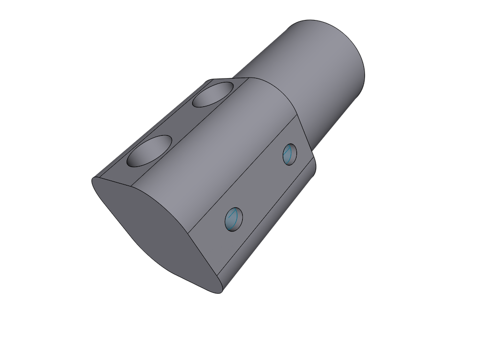 The 3D printed bracket, displaying holes for the radiating elements and tuning screws.
Assembly
Prep cable and balun
For VHF or lower frequencies, make a balun by winding a pair of enamel copper wires 9 times through a T50-17 toroid, or a larger toroid if you’ll be using high power. I use the 17 type toroid for antennas between 20MHz and 200MHz. Solder one end of the pair to your coax cable, keeping the leads as short as possible. Solder the other end of the pair to two nuts, again, keeping leads as short as possible but leaving enough room for the nuts to line up with the small holes in the 3D printed mount. Filing one side of each nut helps make the solder stick to it.
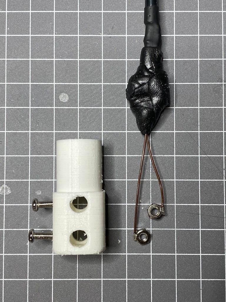 The wound toroid, covered in sealant tape, soldered to the coax cable and nuts.
I’ve had mixed results using a toroid for higher frequencies, such as 70cm. You may want to opt for an air-wound balun instead and solder the coax directly to the nuts to shorten the leads as much as possible. Larry Nelson (K5IJB) has a great article for the same antenna using the air wound balun approach.
Cut two radiating elements
This antenna is a vertical dipole; a balanced antenna that needs two quaterwave radiating elements. In practice I’ve found the final lengths to be slightly shorter than a calculated quaterwave length, but this antenna needs a little extra to support the aluminium rod in the 3D printed mount. Below are my recommended lengths for each element, however, I recommend starting with longer lengths that you cut shorter while tuning on the ground. Then make the final adjustments with the antenna in its operating position using the screws described in the tuning section below.
| Band | Frequency | 1/4 Wavelength |
|---|---|---|
| 2m | 146.500MHz | 530mm for each element |
| 70cm | 439.000MHZ | 190mm for each element |
Assemble antenna
Thread the cable and balun through the plastic pipe and into the 3D printed mount. You might want to glue the 3D printed mount into the pipe, however, mine was quite snug with enough strength to tolerate the wind. Feed the aluminium rods through the larger holes in the 3D printed mount, and fasten them using the screws.
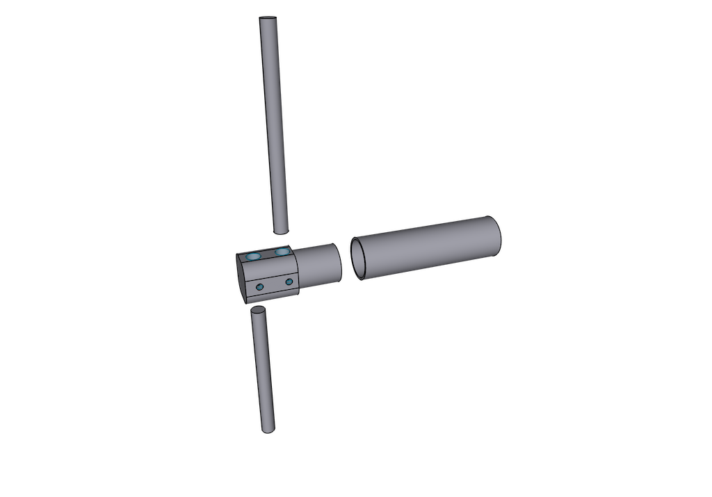 An exploded image of the vertical dipole antenna, displaying the 3D printed mount, two antenna elements and mounting pipe
Tuning
With the antenna in place, adjust the length of the radiating elements and fasten in place by tightening the screws. Note, the screws need to be tight before you measure the VSWR because they make the electrical contact with the aluminium rods.
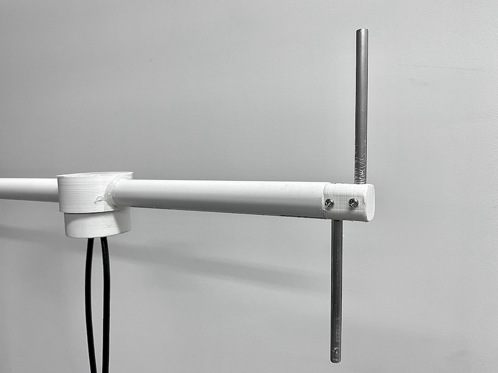 The two tuning screws hold the aluminium radiating elements in place.