Large transmitting loop antenna
Playing with High Frequency (HF) radio is tricky when you live in a unit with limited space. As we know, this is because the lower the radio frequency the larger the antenna you need, at least to do anything meaningful.
My aim was to get onto the 40 meter band (7MHz). Previously I’d been able to get onto this band at home by using a long wire antenna that I’d throw over the roof, coupled with a home-made L-match tuner. This arrangement was temporary, however, and required time to set up and dismantle. I needed a more elegant solution.
I start to investigate smaller options which led me to magnetic loops. Their small but efficient properties are perfect for my environment, and as long as I built one that fits through my garage door I’d be able to deploy and pack it up quite quickly. I’m very happy with my loop - it’s allowed me to make phone contacts to NSW and South Australia, and FT8 (digital) contacts to New Zealand. I was operating at 6W on a little Yaesu FT-818, and I didn’t even need to wheel the loop out of my garage to make these contacts!
Design & materials
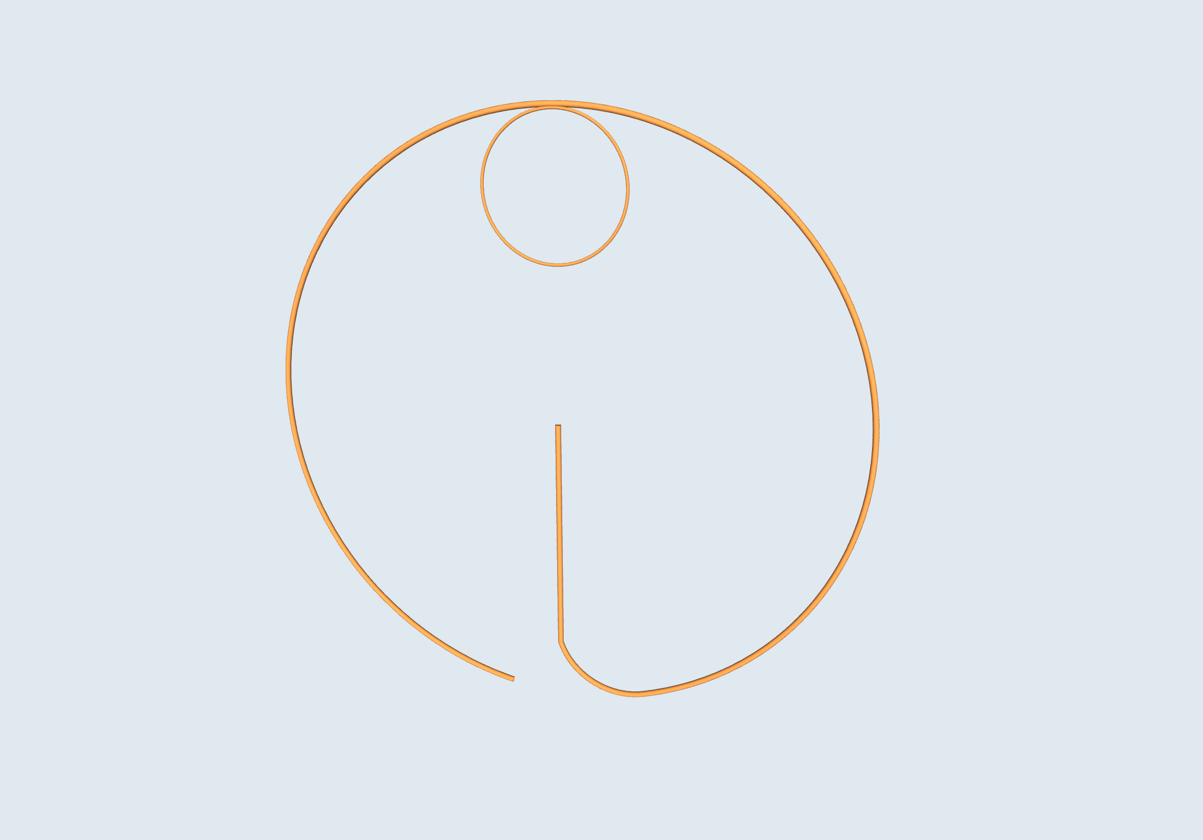 Arrangement of the main and active loops. The upright vertical component hosts the additional metal tubes that form a capacitor.
List of materials
| Component | Size / notes |
|---|---|
| Copper pipe (for main loop) | 19mm OD |
| Copper pipe (for active loop) | 10mm OD |
| Outer aluminium pipe (for capacitor) | 25mm OD |
| Inner aluminium pipe (for capacitor) | 12mm OD |
| Main loop diameter | 1950mm |
| active loop diameter | 390mm |
| Rotary servo | If you want remote tuning |
| Wife-enabled Arduino | Provides the interface to drive the rotary servo |
| 7v battery | Powers the remote tuning mechanism |
The servo suspends the capacitor assembly if you want remote tuning. I used a continuous rotation Pulse Width Modulated (PAM) servo.
I used two online calculators to settle on my final design. The first calculator supports multi-turn designs and shows you the equations used for each calculation, which is great to learn from: Comtech calculator
The second calculator is simpler but effective in giving you key parameters you need to design your loop: 99 pacific calculator
In addition, I found Jeri Ellsworth has a fantastic video demonstration on how the voltage and current flows through a loop.
I spent most of my design time deliberating on the loop size, material and number of turns. In the end I settled on a single turn since multiple turns would have made the build more complicated for a small gain in efficiency. I found some 19mm copper tube on eBay for the main material of the loop, although I was tempted to grossly increase the thickness of the loop material using air-ducting as seen in this YouTube video by Daniel Tooker
I built my loop on a small furniture trolley that wasn’t being used, so that I could easily wheel it around. Being a directional antenna, this also makes it easy for me to turn when I want to null-out interference.
Capacitor
The component holding up the progress of my project was the capacitor. Air variable capacitors are hard to find, and vacuum variable capacitors are very expensive. I tried to make my own air variable capacitor by cutting thin sheets of aluminium but my handiwork wasn’t up to the mark. So, I took inspiration from Dennis Blanchard (K1YPP) who uses tinfoil and metal pipe to form a capacitor, and Peter Parker (VK3YE) who did the same with coax cable and two pieces of circuit board. Peter also has a video on using tinfoil to make a capacitor.
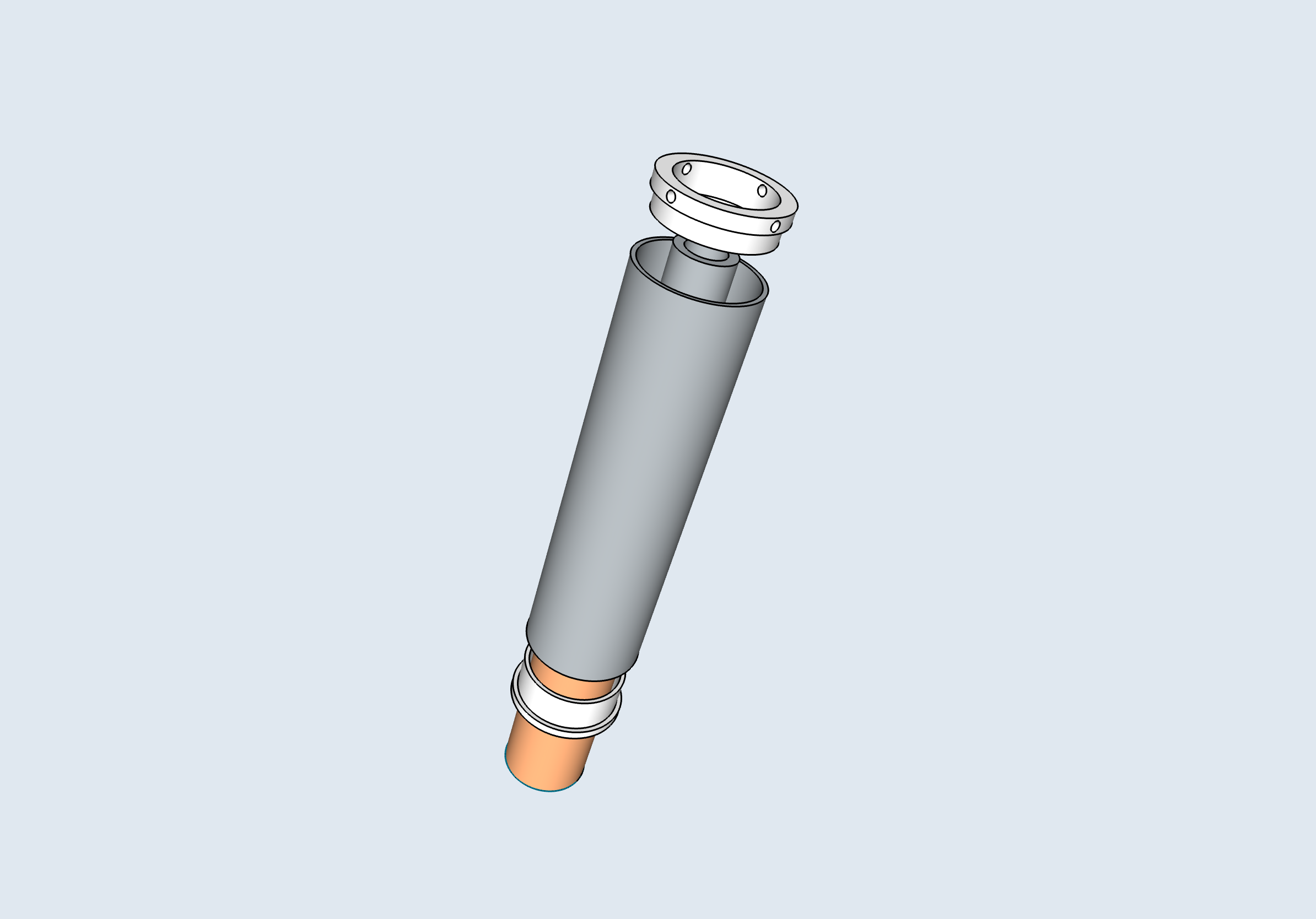 The capacitor design, using interlocking metal tubes. The copper loop is in the centre, while an outer and inner tube slide horizontally to change the value of the capacitor and tune the loop. 3D printed spacers stop the tubes from making contact.
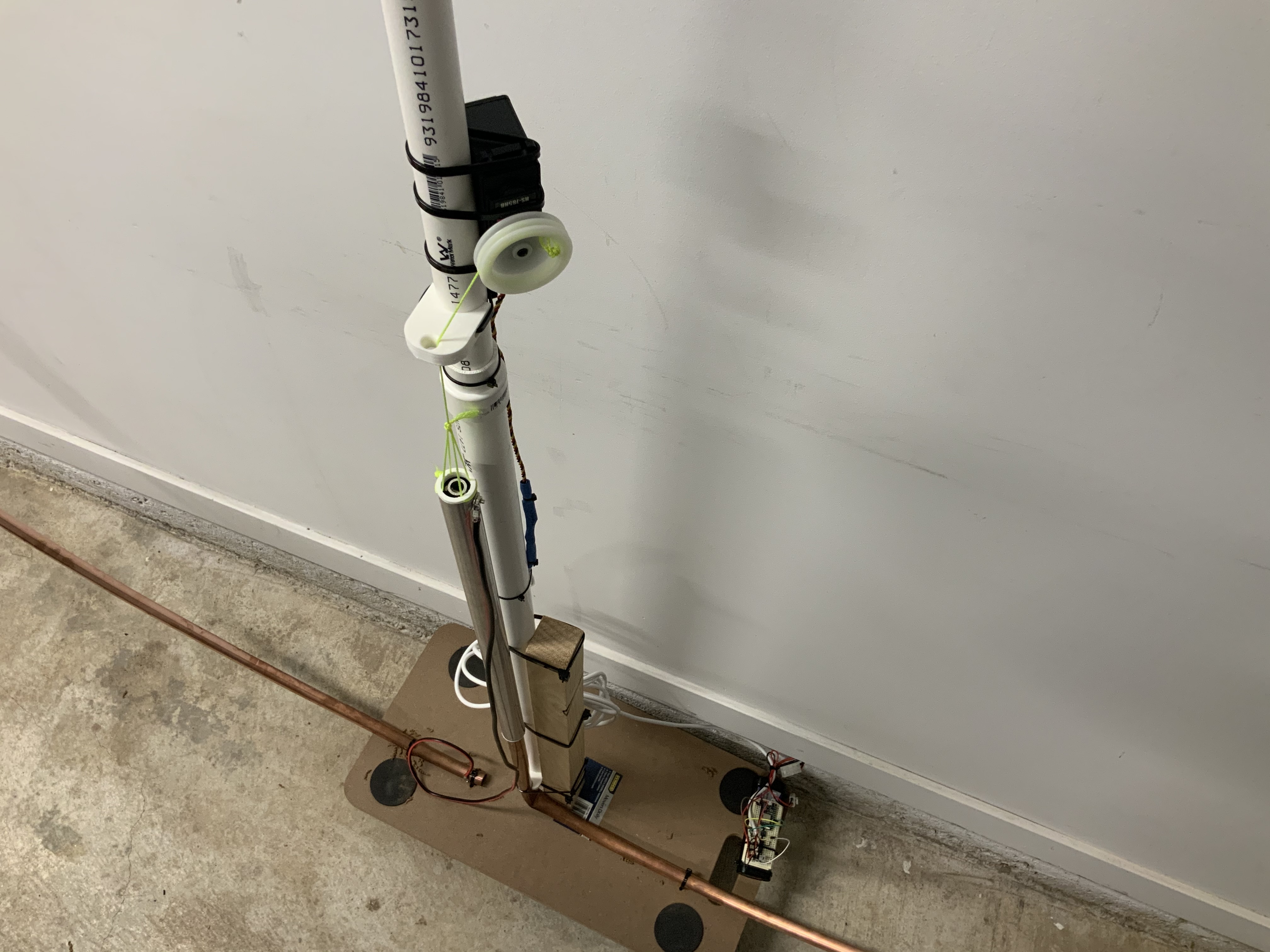 Photo of the capacitor, tuning servo and WiFi enabled microcontroller (Arduino)
My solution was to run two metal pipes over one another to create the capacitive effect required at the bottom of the loop. I started with a single metal rod hung over the vertical copper pipe till Frank (VK3OP) and Greg (VK3CN) gave me the smart idea to add a third metal rod to the system to further increase the capacitive effect and allow my loop to tune down to the midpoint of the 80 meter band. The current effective range of the antenna is 3.5MHz - 10MHz.
You can see a video of my tube-based capacitor here
I’ve been operating at 6W and haven’t experienced any arcing within the capacitor. I’d pay attention to the capacitor at higher power levels to make sure there is no electrical arcing, in which case the diameter of each tube within the capacitor may need adjustment.
This solution was supposed to be temporary while I found a ‘real’ capacitor but I’m very happy with the results. Instead of replacing it I’m going to iterate on the design, perhaps adding more metal to the capacitor or adding a fixed capacitor in parallel to cover the remainder of the 80 meter band.
Automatic Tuning
You’ll see the capacitor tubes are suspended from a rotational servo, which in turn is connected to a WiFi enabled microcontroller and battery strapped to the base of the antenna. I’ve written some code that allows me to calibrate the tuning before I operate, thereafter, I can submit a frequency to the microcontroller and it will move the capacitor, and hence tune the loop, to the corresponding position and frequency. This allows me to quickly tune the loop without having to: a) Change frequency quickly without moving away from the radio, b) or risk electrical shock if the radio starts transmitting in a digital mode while I’m touching the antenna.
Next steps
This Antenna is very much a prototype and I plan to tidy it up. The following are a few items I want to improve, but if you’ve read this far I’d value your input and ideas, too!
- I want to replace the PVC pipe that holds the main loop with something more rigid, probably wood.
- The rotational servo creates electrical noise, and so I adjusted my code to turn it off once it’s finished tuning. However, without energy supplied to the servo, gravity often takes over and the capacitor tubes slide down and de-tune the antenna. I want to replace the rotational servo with something that’ll hold its position when turned off.
- The rotational servo also struggles to accurately position the capacitor, so its replacement will also have more torque and accuracy. I’m thinking of using a geared stepper motor.
- I’m not sure the active (smaller) loop is the most optimal size so I’d like to experiment with different sizes and shapes.
Stay tuned (pun intended!) for more updates!